新闻动态
Key points and warnings for controlling the oil content in the compressed air system
责任编辑:作者:admin人气:143 发表时间:2025-07-22
Xi'an Ultrafiltration Li Daming Jin Yonggui
Introduction: Recently, a large-scale oil contamination was discovered in the high-pressure compressed air pipeline system of a certain factory, posing a significant threat to subsequent gas-using points. Through on-site investigation, experiments, tests, and adjustments, the oil contamination phenomenon has been effectively controlled, and subsequent corrective measures have been initiated. This article analyzes and proposes suggestions regarding the formulation of oil content indicators for compressed air/gas systems, the selection and application of air distribution equipment, especially oil removal equipment, as well as corresponding oil content testing methods and detection instruments. The viewpoints and oil removal/testing methods, measures, and certain commercial misleading phenomena proposed in this article have certain reference and warning effects for both manufacturers and users.
1. Air source system and equipment:
1.1, Gas source system process:
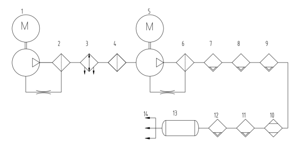
① Injection screw ② Oil separation (at high temperature) ③ Secondary water cooler ④ Inefficient gas-liquid separator
⑤ Piston compression unit ⑥ Gas-liquid separator ⑦ Pre-filter ⑧ Precision oil removal filter
⑨ Ultra-precision oil removal filter ⑩ Dryer ⑾ Dust removal filter ⑿ Precision dust removal filter ⒀ Storage cylinder ⒁ Gas supply network
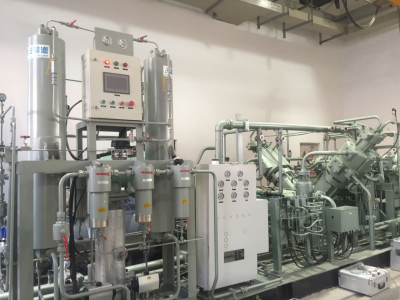
1.2, Oil Source and Oil Removal Equipment:
This system is a high-pressure gas source. It adopts a new process of screw + piston. Both the two-stage booster units are equipped with oil-lubricated design.
The low-pressure section uses an injection screw. The injection volume is approximately a volume ratio of 100:1, that is, 10 liters of oil need to be injected for every 1 cubic meter of air intake. The injection functions include: cooling, lubrication, sealing, and noise reduction. The injection volume depends on the cooling requirement during the compression process. The pressurized gas tangentially enters the oil separator tank and is separated into most of the oil droplets by centrifugal separation. After cooling, it returns to the suction port of the compressor. The remaining oil mist (0.01μm to 0.5μm) passes through ultra-fine glass fiber precision oil filtering elements to be condensed into larger liquid droplets and fall into the bottom of the inner cylinder of the filter element. They are then pressed back to the suction port through a small diameter pipe. Thus, the vast majority of the injected oil is recycled. However, there will still be a small amount of suspended oil and a certain amount of oil vapor entering the piston compressor inlet with the gas.
The second-stage piston compression unit is of multi-stage compression. The lubrication method is oil injection, that is, a high-pressure oil pump injects lubricating oil into the small holes on the inner wall of the cylinder, forming an oil film with the high-speed reciprocating piston ring. The injection volume can be adjusted by the rotational speed of the pistons in each stage of the plunger pump. The injected oil is mostly cooled by the inter-stage and terminal coolers and mixed with condensate water in the subsequent separator for separation and discharge. A small amount of suspended oil droplets and oil vapor are carried by the high-pressure gas into the subsequent filtration and drying device for oil removal, drying, and dust removal, and finally supply the downstream with dry product gas without oil, water, or dust.
1.3 Oil content form and distribution pattern:
ISO8573-2-96 "General Use of Compressed Air - Part 2: Test Method for Suspended Oil Content" provides the typical states and quantity ranges of oil at different sampling locations.
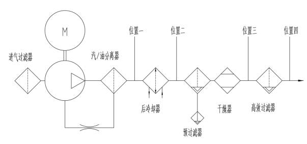
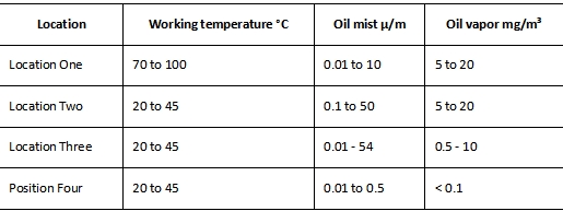
The US company SPX has conducted more detailed tests and descriptions for Position One and Position Four.
Table 2: Oil/Gas Ratio of Injected Screw Oil at Different Temperatures
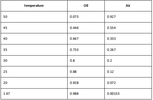
The above text and charts reveal the following phenomena:
The oil injection screw can absorb a large amount of oil. The oil is filtered and deoiled under high-temperature conditions. The oil content at the outlet cannot be ignored. Especially, the oil vapor can pass through the oil filter element without any obstruction. According to statistics, the total amount of oil carried by the gas is approximately 20-30 mg/m3. For general industrial applications, a cooler and an efficient oil removal filter should be installed after it.
② As the temperature decreases, the oil vapor will significantly transform into oil aerosols. The extent of this transformation is much greater than that of water vapor converting into liquid water. For every 10℃ drop in gas temperature, approximately 50% of the water vapor condenses into liquid water, while the condensation conversion rate of oil vapor is nearly 70%. Therefore, reducing the temperature of the compressed air is beneficial for improving the efficiency of oil filtration.
③ If the user does not care about the total hydrocarbon content or the absolute oil content, the influence of oil vapor can be disregarded when using gas at temperatures above 40℃. However, if the gas is used at low temperatures or in the absence of oil at all, such as in space, oxygen, electronics, etc., the removal of oil vapor must be considered.
2. Test methods and testing instruments:
Since the 1960s, there have been applications in China for measuring oil content indicators from gases, such as the introduction of the Soviet Union's oil content indicator: 3×10⁻⁷ (volume ratio), which is equivalent to the current international standard unit of 3mg/m3. The sampling method mostly involves gas passing through solvent absorption or using a solvent to clean the sample and then comparing the spectrum with the standard oil sample under an infrared spectrophotometer. This method varies depending on the sampling method or whether it measures the total oil content or only detects suspended oil. At the end of the last century, China's power air compressors began to replace piston machines with oil-injection screw compressors, and the replacement rate has reached over 90%. One of the most important performance parameters of the oil-injection screw compressor is the residual oil content in the exhaust, which is also the most dreaded topic for air compressor manufacturers, component suppliers, purification equipment producers, and various distributors and agents. In the 21st century, the three major indicators of compressed air quality: oil, water, and dust, have achieved breakthroughs and popularization in testing instruments and methods. However, due to the numerous defects and operational difficulties in oil content testing from theory to practice, the water and dust have not yet achieved maturity and popularity. In recent years, some simple, online, and portable methods have emerged, such as the chemical reagent method of Johnson in the United States and Degger in Germany, as well as the latest optical refraction method. The measurement range can reach 0.01 to 10mg/m3, but they can only measure oil and cannot measure oil vapor simultaneously. Considering the mature technology of the condensation oil removal filter, its residual oil content can be measured down to 0.001mg/m3, with a reliability of at least 0.01mg/m3, which basically meets the needs of modern industry and even high-tech and special fields. At the same time, the non-negligible nature of oil vapor pollution has also been recognized. In recent years, some specialized factories, including purification equipment factories and instrument and metering instrument factories, have launched several test instruments specifically for oil vapor, such as the portable residual oil detector CS120 used in this case, which uses PID (sensor) and has a measurement range of 0.001 to 10mg/m3. The online measurement results are highly consistent with the data from the infrared method.
3. Conclusion:
3.1 Revelation:
With the development of oil-free/oil-reducing technologies at the air source side and residual oil content detection technologies, there are no longer any obstacles for domestic applications to control the residual suspended oil in compressed air/gas to be within the range of 0.3 to 1 mg/m3. Similarly, controlling the oil vapor to be within the range of 1 to 10 mg/m3 can also be achieved by using activated carbon adsorption technology in specific application fields, which can reach 0.03 to 1 mg/m3.
② Since the oil/gas ratio is closely related to temperature, users need to select the appropriate residual oil content index based on their own conditions and requirements and further subdivide it. For example, for general power gas sources, they operate at normal temperature and are equipped with a condensing high-efficiency oil removal filter. Oil vapor can be ignored in such cases. However, in environments where oil is prohibited or at low temperatures, the presence of oil vapor must be taken seriously to avoid the risk of oil contamination.
In the figure 1 of this article, between ④ and ⑤ (i.e., between the outlet of the separator and the inlet of the piston compressor), a precision oil removal filter is added; between ⑩ and ⑾ (i.e., between the outlet of the dryer and the inlet of the dust removal filter), a large-capacity activated carbon adsorber is added. The former can effectively reduce the oil content in the output gas of the injection screw compressor, while the latter can remove the vast majority of oil vapors generated by the two compressors.
3.2 Warning:
The oil-injection screw pump and oil remover cannot replace the oil-free compressor (centrifugal compressor, oil-free screw pump, oil-free piston machine). They should be used with caution especially in environments where oil is prohibited or in low-temperature conditions.
② Without a post-cooling stage and a precision oil remover, the oil-injected screw compressor generally cannot meet the oil content requirements of ordinary compressed air users.
③ High temperatures generate high concentrations of oil vapors and reduce the adsorption capacity of activated carbon. Therefore, oil removal (including suspended oil and oil vapors) equipment must operate at lower temperatures.
④ Due to the different working principles, the suspended oil and oil vapor tester and the other tester must not be used simultaneously.
⑤ Manufacturers, distributors and agents of air compressors and purification equipment must not induce customers to make incorrect selections, which could result in excessive residual oil content in actual applications or overly inflated indicators.
上一篇:CNG汽车加气站脱水装置 应用体会与分析
下一篇:暂无


